P & P Precision Designs Limited
foam welding and laminating machines


Foam Butt Welder » Operating Instructions
OPERATING INSTRUCTIONS
Issue 1 March 2001
P&P Precision Designs Ltd
Butt Welder Mk 2
|
INTRODUCTION |
APPENDICES: BUTT WELDING CONDITIONS
Appendix 1 LD based products
Appendix 2 EV and VA based products
Appendix 3 HD and HL based products
Butt welding is the process of
joining butt surfaces (edges) together by heat to form rolls of
material with a weld equivalent in strength to that of the
individual sheets. The machine clamps the two blocks of foam, then
compresses the edges together, then uses an electrically heated
blade that passes along the joint to weld the butt surfaces:-
i) Density: High density grades require more heat to melt an
equivalent surface area.
ii) Grade: Amount of heat required to melt a sheet surface depends
upon the melt properties of the base polymer e.g. HDPE has a higher
melting temperature range than LDPE.
iii) Butt Contact Pressure: Amount of pressure applied to the joint,
this is determined by how the machine is calibrated.
CONTENTS PART 2 CAPABILITIES OF THE P&P MK 2 BUTT WELDER
2.1 Use of Butt Welder
The machine is designed to weld Plastazote, Evazote and Supazote foam grades produced by Zotefoams.
2.2 Width
Maximum foam width of up to 1500mm
can be welded.
However there are other factors
which affect the laminated width achievable which are not related to
the design of the butt welder. The maximum width achievable depends
upon the squareness of the sheets at the edges and the alignment of
the edges as they are being fed-in.
Misalignment becomes more
important when building up long reels as the roll will not continue
straight and true along the length.
2.3 Butt Welded Reel Length
The only limit to the length of the
reel that can be produced is the difficulty of handling long reels and
ideally this requires specialised handling equipment.
2.5 Thin Sheet Foam
Altering the height of the top
clamps to accommodate foam thinner than 30mm will render the machine
potentially unsafe – The CE Mark and hence the minimum closure
distance of the clamps (25mm) has been determined using EN 294,
‘Safety Distances to Prevent Danger Zones Being Reached By Upper
Limbs’.
2.6 Rate Of Butt Welding
This is controlled by the speed of
the traversing blade, which is adjustable from the control console.
2.7 Butt Welding Temperatures
Temperature can be set in 1°C
increments up to a maximum of 550°C, which is adjusted from the
temperature controller on the console. There are specific
temperatures for particular materials, as shown in the appendices,
however, these can altered to suit particular requirements.
2.8 Weld Hold Time
Because this is similar for most
materials, ie. 5 seconds, the machine is set this way as standard.
This can be adjusted to particular requirements using the E-200 user
interface. Please refer to the ‘Electrical and Control Manual’.
CONTENTS PART 3 MACHINE OPERATION
3.1 Introduction to Operation
The
butt welder operates by
clamping two sheets of foam on either side of the electrically
heated blade. The ‘butt’ surfaces are compressed together and the
heated blade then passes across the join, welding the sheets
together.
3.1.1 General Operation
Before attempting to operate the
butt welder the user must be fully conversant with the Health and
Safety Section (Part 4) of these instructions as well as being fully
familiar with the location of the Emergency Stop button and all the
operational buttons and switches.
The Emergency Stop button isolates
power to all of the active systems and the heater blade.
The Emergency Stop button is also
used to put the machine into standby mode.
3.1.2 Sequence of Operation
a. Turn on machine and allow blade
to reach set temperature.
b. Reset the machine using the Joy-Stick.
c. Push in foam to either side of machine, ensuring foam is spread
evenly over clamp-feet-pairs and butted-up to the spacer.
d. Clamp down using Right Clamp Down Joy-Stick.
e. Carry out same procedure for Left Clamp Down.
f. Start weld sequence using Joy-Stick.
g. Allow weld sequence to complete.
h. Clamps will automatically release after a set delay.
i. Remove the two joined pieces from the machine.
j. Reset using the Joy-Stick.
3.1.3 Sheet Feeding
Foam guides are located at each side
of the machine to ensure sheets of foam line
Up. At the start of production of a new batch, these guides should
be adjusted
According to the width of foam being welded.
3.1.4 Foam Characteristics.
Successful
butt welding relies upon the contact surface maintaining even
heat transfer. The heat transfer from the blade depends upon:
i) Density High density grades require more heat to melt the
surface.
ii) Grade Heat required to melt sufficient of the material surface
depends upon the melt characteristics of the grade.
iii) Contact Surface area in contact pressure with the blade depends
upon the Gap Settings (Figure 1).
3.2 Blade temperature
3.2.1 Adjusting the Temperature
Controller
The set temperature is controlled
and adjusted by a Temperature control unit.
With power on, two temperatures are
continuously displayed, the lower being the `Desired Temperature',
the upper the actual blade temperature.
The `Desired Temperature' is
adjusted by the operator touching the front of the panel below the
displayed temperatures. The up and down buttons will illuminate and
pressing either button will change the set point value. Short
presses change the set point by single units. Long presses
accelerate the set point for large adjustments.
3.2.2 Setting the Correct Butt
Welding Temperature.
i) Temperatures must first be set
up as specified in the Appendix for the specific grade and
thickness.
ii) After start-up from cold allow heated blade to maintain set
temperature before using.
3.2.3 Using Temperatures
Higher than the Operating Temperatures
Setting the temperature slightly higher than
indicated in the Appendices may improve the weld when sheets are
uneven. However, in excess of 20°C - 68°F higher may result in
unsatisfactory weld quality.
i) The blade temperature should be kept as low as possible. In the
event of the blade becoming trapped while in contact with the blade,
the higher the temperature the greater the risk of fire.
ii) Unnecessary over-heating of material may give a thicker, darker,
more prominent weld line.
iii) Material will be more prone to sticking to the blade and uneven
melt-back will be more likely to occur; i.e., gaps and solid lumps
giving very poor quality weld.
iv) Over-heating and material sticking to the blade will result in
the emission of excess smoke and fumes.
3.3 Blade Traverse speed
3.3.1 Adjusting the Blade Speed
The 0-99 touch-dial on the operators console
controls the speed of the blade:-
The machine is normally used at full speed, although, the speed can
be lowered to suit particular requirements.
3.4 Foam Dimensional Tolerances
FOAM DIMENSIONAL TOLERANCES ARE
CRITICAL TO PRODUCING A QUALITY WELD.
IF THE FOLLOWING PRE-REQUISITES ARE NOT STRICTLY ADHERED TO, WELD
QUALITY WILL BE POOR.
The edge of the foam to be
welded requires to be sawn using a ‘band saw’.
THE SAW LINE CAN NOT DEVIATE MORE THAN 1MM FROM ONE END TO THE
OTHER.
The squareness of the saw cut
is also critical.
THE SQUARENESS OF THE SAW LINE CANNOT DEVIATE MORE THAN 1MM FROM
TOP TO BOTTOM.
CONTENTS
3.5 Butt Welding Dissimilar Materials Together
Use the conditions for the foam
with the highest set points
i.e. The highest temperature and the
slowest blade speed.
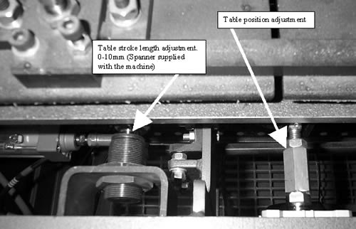
Figure 1 - Table Compression adjustments

3.6 Compression adjustment
Altering the location of the shock
absorber (Fig 1) allows the contact pressure to be altered.
The greater the distance the greater the stroke of the cylinder.
When resetting this distance ensure all four are set to exactly the
same distance.
3.6 Table position adjustment
This is adjusted at the
connection to the pneumatic cylinder. This should never need to be
altered. If adjustments are made for any reason, such as for
maintenance, ensure they are repositioned exactly. Failure to do so
could cause catastrophic damage to the machine.
CONTENTSPART 4 HEALTH AND SAFETY
Any machine can be dangerous if
improperly used.
Safe working practice is the responsibility of the user.
Note that this machine contains pneumatic clamps and a hot blade
that must not be touched.
1. This
machine must be properly and safely installed on a firm and
level base.
2. Operators must be fully
trained in the safe use of this machine.
3.
This machine must only be used for the purpose it is intended.
4. This machine incorporates fixed guards which
must not be removed.
5. All users must be
fully aware of the location of the Emergency Stop button.
6. The machine must be electrically isolated
before obtaining access to any part of the machine.
7. It is recommended that an Extraction Hood be fitted
over the machine to duct away any fumes.
8.
Under no circumstances should anybody reach inside the tunnel
guard.
9. In the event of the machine
stopping during welding and cannot be restarted normally, no
attempt should be made to clear the obstruction until it is
cooled. In the unlikely event of a fire, suitable fire
extinguishers must readily available.
10.
Operators must not wear loose clothing or items that may become
trapped in the moving parts.
11. In addition
to the above requirements local regulations on health, safety
and welfare in the workplace must be followed.
TABLE 1.1 : Traversing Blade
Butt Welder Conditions for LD based products
Materials with ‘strike-through’ (LD24LC)
have not been tested for butt welding as they were deemed unsuitable
for producing reels.
|
Product Grade |
Optimum Operating |
Speed Setting |
Vertical Clamp |
|
LD15 |
440 |
99 |
1.5 |
|
LD18 |
440 |
99 |
1.5 |
|
LD24 |
440 |
99 |
1.5 |
|
|
|||
|
|
|||
|
LD33 |
450 |
99 |
3.5 |
|
|
|||
|
LD45 |
460 |
99 |
3.5 |
|
LD60 |
480 |
99 |
3.5 |
|
LD70 |
500 |
70 |
3.5 |
CONTENTS
APPENDIX 2
TABLE 2.1 : Traversing Blade
Butt Welder Conditions for EV & VA based products
Materials with ‘strike-through’ (LD24LC)
have not been tested for butt welding as they were deemed unsuitable
for producing reels.
|
Product Grade |
Optimum Operating |
Speed Setting |
Vertical Clamp |
|
VA25 |
450 |
99 |
1.5 |
|
VA35 |
460 |
99 |
1.5 |
|
VA65 |
500 |
99 |
3.5 |
|
|
|||
|
EV30 |
470 |
99 |
1.5 |
|
EV50 |
500 |
99 |
1.5 |
|
|
|||
|
|
CONTENTS
APPENDIX 3
TABLE 3.1 : Traversing Blade
Butt Welder Conditions for HD and HL Based Products
Materials with ‘strike-through’ (LD24LC)
have not been tested for butt welding as they were deemed unsuitable
for producing reels.
|
Product Grade |
Optimum Operating |
Speed Setting |
Vertical Clamp |
|
HD30 |
500 |
99 |
3.5 |
|
|
|||
|
|
|||
|
HD115 |
|||
|
HL34 |
480 |
99 |
3.5 |
|
|
|||
|
|
CONTENTSTRADEMARKS
PLASTAZOTE, EVAZOTE and SUPAZOTE are registered trademarks of Zotefoams plc.
FOAM LAMINATOR
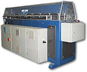
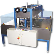
The P&P Laminator operates by passing two foam sheets either side of an electrically heated blade which melts the sheet surfaces.
FOAM BUTT WELDER
The P&P Butt Welding machine has been developed to produce a fast clean weld with no distortion to the joint surface.

